Showing posts with label Help. Show all posts

Monday, February 29, 2016

Viewing applied temperatures

If you are concerned about thermally induced stresses in your design, you will want to run a thermal analysis to determine the temperature distribution. Then, map the temperature results to a subsequent structural analysis.
Mechanical Event Simulation (MES) allows a user to apply such temperatures automatically, whether from a steady-state or transient heat transfer analysis.

If you have previously run a transient thermal analysis, you may want to ensure that the mapping algorithm used for transferring the temperatures to an MES analysis has worked as expected. After all, you could be using different mesh sizes for each analysis type, and the nodal temperatures may not map one-to-one from a transient thermal analysis to an MES analysis.
So how do you check if the mapping was done correctly?

Here is how:

In this example, the FEM file is located in the following folder (C:\FEA\Bracket.fem)

Let’s say that, in Design Scenario 1, you conducted a Transient Heat Transfer analysis on an Assembly using a 100% mesh size. 


Then, you created a second Design Scenario as an MES analysis and meshed it with a 50% mesh size. You then applied the thermal loads within the Thermal tab of the Analysis Parameters dialog. 


Before running the MES analysis, simply perform a “Check Model” operation. This action creates the solid mesh and decodes the geometry, loads, and constraints. If you look in the Design Scenario 2 folder (C:\FEA\Bracket.ds_data\2), you will now see a file named “ds_map.tto”, which is a transient temperature output file mapped from Design Scenario 1 to Design Scenario 2.


At this point, change the analysis type from MES to Transient Thermal, creating a 3rd Design Scenario. Keep the same mesh size (50%) as used in the MES analysis.

Using Windows Explorer, copy the file “ds_map.tto” from “C:\FEA\Bracket.ds_data\2” to “C:\FEA\Bracket.ds_data\3”.  Then, rename the copied file “ds.tto” (deleting “_map” from the name).


Within Simulation Mechanical perform a “Check Model” operation for the 3rd design scenario, which is the second transient thermal analysis, without applying any loads or constraints. 

In the Results environment for design scenario 3, you will now be able to see the temperature results that were mapped from Design Scenario 1 (utilizing a 100% mesh size) to Design Scenario 2 (utilizing a 50% mesh size).   


Saturday, March 22, 2014

Understanding Degrees of Freedom

For finite element analysis (FEA) users, it's important to keep in mind that some types of elements might not transmit all types of loads through their nodes. For example, two structural beam elements connected together behave like a fully welded connection because the beam elements will transmit three forces (axial and two shears) and three moments (torsion and two bending). However, a beam element connected to a truss element behaves like a pinned joint because the truss element can only transmit axial forces. The concept of what forces are transmitted and consequently what loads and restraints can be applied is known as degree of freedom (DOF).

The DOF is important to understand in determining how loads can be applied, how boundary conditions restrain the model and how different element types need to be connected together. A translational DOF indicates that forces are transmitted through the nodes and a rotational DOF indicates that moments are transmitted through the nodes.
For example, two-dimensional (2-D) elements only have translational DOFs. Thus, you cannot apply a nodal moment to a 2-D element; mathematically, the element cannot react to the moment.


Figure 1: 2D Elements (Triangular)

Figure 2: 2D Elements (Quadrilateral)

In addition, a "fully fixed" boundary condition cannot provide a moment restraint to a brick element because brick elements only have translational DOFs.
Figure 3: Brick Elements (8 noded)

Finally, the beam to truss element connections could be unstable because the truss element will not prevent the beam element from rotating; if the other end of the beam is free to translate, then the connection behaves like a ball joint.

Figure 4: Beam Element to Truss Element connection

The last two examples may result in model stability messages (such as "model not tied down enough") during a linear static stress analysis.

Table 1: DOFs for common structural element types.
Element
Degrees of Freedom
Truss
translation in X, Y, Z
Beam
translation in X, Y, Z; rotation in X, Y, Z
2-D
translation in Y, Z
Brick
translation in X, Y, Z
Plate
translation in X, Y, Z; Two in-plane rotation DOFs
(The out-of-plane rotational DOF is not considered for plate elements)

Note: This is a small subset of the available element types in Autodesk Simulation Mechanical software, see the User's Guide for a full list.


Friday, March 21, 2014

How to define surface contact in 2D analyses

For linear static stress analysis of two-dimensional (2-D) assembly models that are created using Autodesk Simulation’s sketching, modeling and meshing capabilities, you can conveniently and quickly define contact between parts. To do so, use the following general method:
  1. Sketch the 2-D parts (the parts must share at least one identical-length, coincident edge).
  2. Select the sketches in the tree view and click on the “Generate 2D Mesh” button within the “Mesh” panel under the “Mesh” tab (see Figure 1). The "2-D Mesh Generation" dialog will appear.

Figure 1: In the tree view, select the sketches that share a coincident edge and then click “Generate 2D Mesh” to access the "2D Mesh Generation" command.
  1. Adjust the mesh settings as necessary and press “Apply” to generate the mesh.
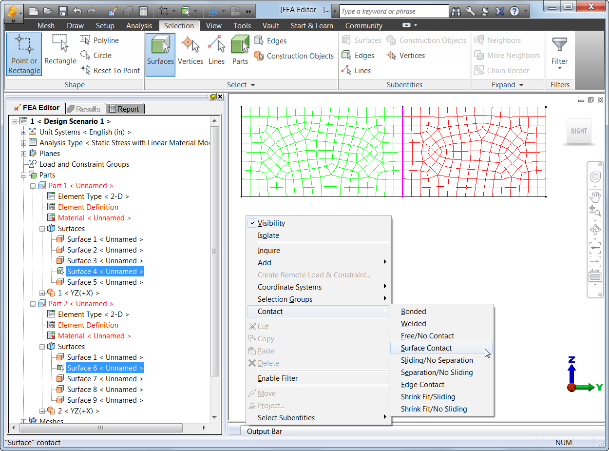
  2. In the model display, select the coincident surfaces and right click. In the pop-up menu, choose "Contact" and then specify the type of contact from five applicable options (see Figure 2):
    • Bonded - The nodes on the two edges will be matched and will be in perfect contact throughout the analysis. When a node on one edge deflects, the node on the adjoining edge will deflect the same amount in the same direction. This is the default option.
    • Free/No Contact - The nodes on the two edges will not be matched and will be free to move relative to each other.
    • Surface Contact - The nodes on the two edges will be matched and will be free to move away from each other. If the nodes move toward each other, a stiffness will be applied to resist this movement.
o   Sliding/No Separation – Bonds contact faces in normal to face direction while sliding under deformation.
o   Separation/No Sliding – Separates contact faces partially or fully without them sliding against each other.
Note that Edge Contact and Welded Contact are not applicable to 2D elements.

Figure 2: Once the mesh is generated, you can select and right click on the coincident surfaces and specify the type of contact.
  1. After defining the type of contact, the contact surfaces will be listed in the tree view.
  2. In the tree view, right click on the contact pair and choose "Settings..." (see Figure 3).

Figure 3: Right click on the contact pair in the tree view and choose "Settings...".
  1. In the "Contact Options" dialog, you can specify the coefficient of friction for the contact pair (see Figure 4).

Figure 4: Choose whether or not to include friction in the analysis and specify the static friction coefficient.
  1. Set up for linear static stress analysis (define element information, material properties, loadings and constraints) and run the analysis.
  2. In the Results environment, you can inquire on the total contact force for each contact pair in the model. Right click on the heading for the contact pair in the tree view and choose the "Contact Force..." command (see Figure 5).

Figure 5: In Results environment, you can inquire on the total contact force. A "Total Contact Force" dialog will appear with the total contact force for that pair.

Thus, the ability to quickly and easily define 2-D contact helps you to perform linear static stress analysis of 2-D assembly models that were created with Autodesk Simulation’s sketching, modeling and meshing tools.


Thursday, March 20, 2014

Useful Links

With the release of Autodesk Knowledge Network (AKN) some of the website you are looking for may have moved around a little. So here are some of the links I find useful

1) Autodesk Simulation Mechanical Accuracy Verification: Link

2) How to install Simulation Mechanical Help locally?  Link

3) How do I download the latest Service Pack for Simulation Mechanical?  Link

4) SIMTV: Link


-Sualp