For
linear static stress analysis of two-dimensional (2-D) assembly models that are
created using Autodesk Simulation’s sketching, modeling and meshing
capabilities, you can conveniently and quickly define contact between parts. To
do so, use the following general method:
- Sketch the 2-D
parts (the parts must share at least one identical-length, coincident
edge).
- Select the sketches in the tree view and click on the “Generate 2D Mesh” button within the “Mesh” panel under the “Mesh” tab (see Figure 1). The "2-D Mesh Generation" dialog will appear.

Figure 1: In the tree view,
select the sketches that share a coincident edge and then click “Generate 2D
Mesh” to access the "2D Mesh Generation" command.
- Adjust the mesh
settings as necessary and press “Apply” to generate the mesh.
- In the model
display, select the coincident surfaces and right click. In the pop-up
menu, choose "Contact" and then specify the type of contact from
five applicable options (see Figure 2):
- Bonded - The nodes on
the two edges will be matched and will be in perfect contact throughout
the analysis. When a node on one edge deflects, the node on the adjoining
edge will deflect the same amount in the same direction. This is the
default option.
- Free/No Contact - The nodes on
the two edges will not be matched and will be free to move relative to
each other.
- Surface Contact - The nodes on
the two edges will be matched and will be free to move away from each
other. If the nodes move toward each other, a stiffness will be applied
to resist this movement.
o
Sliding/No Separation – Bonds contact
faces in normal to face direction while sliding under deformation.
o
Separation/No Sliding – Separates contact
faces partially or fully without them sliding against each other.
Note that Edge Contact
and Welded Contact are not applicable to 2D elements.
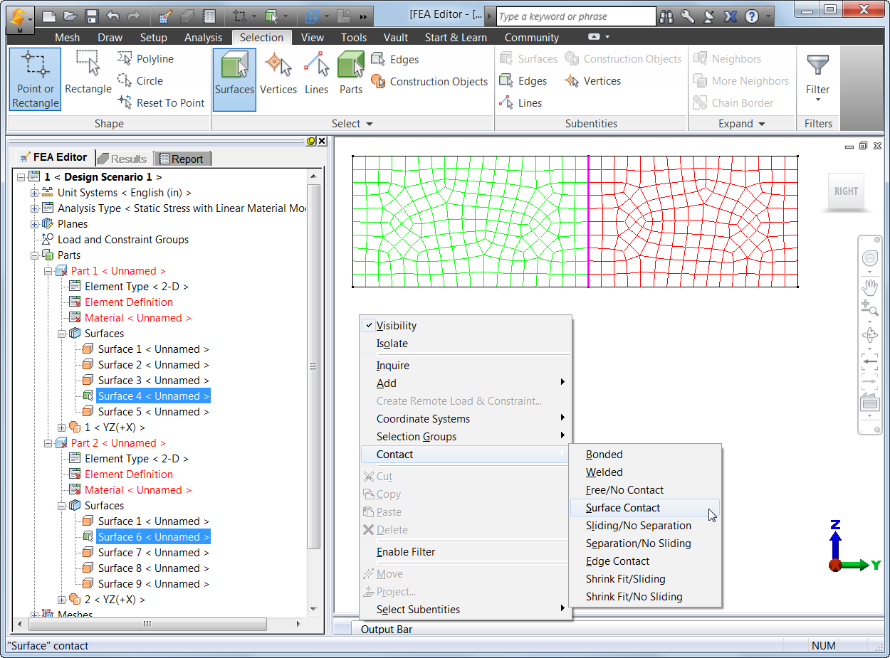
Figure
2:
Once the mesh is generated, you can select and right click on the coincident surfaces
and specify the type of contact.
- After defining
the type of contact, the contact surfaces will be listed in the tree view.
- In the tree
view, right click on the contact pair and choose "Settings..."
(see Figure 3).

Figure 3: Right click on the
contact pair in the tree view and choose "Settings...".
- In the "Contact
Options" dialog, you can specify the coefficient of friction for the contact
pair (see Figure 4).

Figure 4: Choose whether or
not to include friction in the analysis and specify the static friction
coefficient.
- Set up for
linear static stress analysis (define element information, material
properties, loadings and constraints) and run the analysis.
- In the Results
environment, you can inquire on the total contact force for each contact
pair in the model. Right click on the heading for the contact pair in the
tree view and choose the "Contact Force..." command (see Figure
5).

Figure 5: In Results
environment, you can inquire on the total contact force. A "Total Contact
Force" dialog will appear with the total contact force for that pair.
Thus,
the ability to quickly and easily define 2-D contact helps you to perform
linear static stress analysis of 2-D assembly models that were created with Autodesk
Simulation’s sketching, modeling and meshing tools.
Merhaba Sualp Bey. Size Samsundan ulaşıyorum.Makine mühendisiyim.Çalışmakta olduğum firma yıllar önce Autodesk Simulation Mechanical programını satın almış.İşe yeni girdim ve benden program ile ilgili analizler yapmam isteniyor.Autodesk Nastran'a dönüp sim. mechanical kısmını bıraktığı için, Çok fazla aramama rağmen programla ilgili tatmin edici dökümana ( özellikle Türkçe ) ulaşamadım.Sizin bana yardımcı olabileceğinizi söylediler.Yardımcı olursanız çok sevinirim.kolay gelsin....
ReplyDelete