When evaluating the results of a linear static stress analysis, one can specify allowable stress values and then display factor of safety contours to see where stresses in the model are below and above those allowables. Viewing factor of safety contours can help one decide whether a design needs modification or is acceptable and is ready for manufacturing.
To display factor of safety contours, choose
the "View" command in the "Safety Factor" dropdown of the “Stress”
panel in the “Results Contours” tab of Autodesk Simulation (see Figure
1).
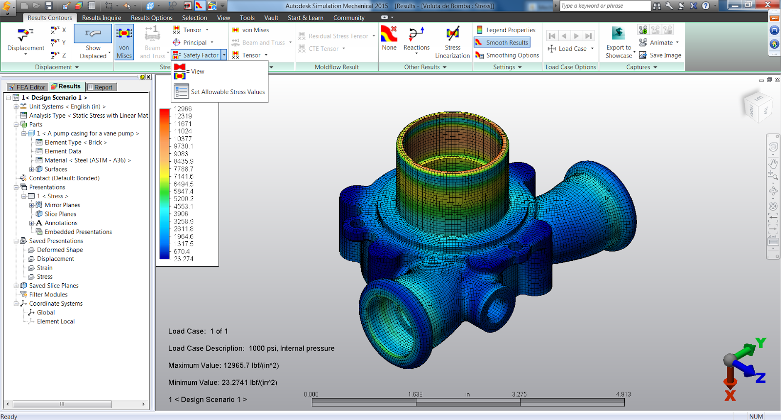
Figure 1: In the "Safety Factor" dropdown, choose the "View"
command to display factor of safety contours.
|
When this command is activated, color-coded
contours of the factor of safety for the selected stress contour will be shown
(see Figure 2).

Figure 2: In the Results environment, one can specify allowable stress
values and then display factor of safety contours. This contour shows a
color-coded graphical display of where stresses in the model are below and
above the specified allowables.
|
The factor of safety is the ratio of the
allowable stress to the actual stress:
- A factor of safety of 1 represents that the stress is at the allowable limit.
- A factor of safety of less than 1 represents likely failure.
- A factor of safety of greater than 1 represents how much the stress is within the allowable limit.
The allowable stresses can be assigned on a
per part basis by choosing the "Set Allowable Stress Values" command
in the "Safety Factor" dropdown (see Figure 3).

Figure 3: Choose the "Set Allowable Stress Values" command in
the "Safety Factor" dropdown to specify allowable stress values.
|
The "Allowable Stress Values" dialog
will appear and each part will be listed in a separate row. One can specify a
value in the "Allowable Stress" column or press the "Load Yield
Stress" or "Load Ultimate Stress" buttons to load the values
from the material library (see Figure 4). Any parts for which the
allowable stress is set to 0 will be excluded from the factor of safety
calculations.

Figure 4: In the "Allowable Stress Values" dialog, one can
enter a value for a part in the "Allowable Stress" column or press
the "Load Yield Stress" or "Load Ultimate Stress" buttons
to load the values from the material library.
|
Thus, the ability to view factor of safety
contours helps engineers determine what the results say about the adequacy of a
design. For example, examining these contours can help you properly
exercise engineering judgment when balancing between material cost reduction
and ensuring a safe product.
No comments:
Post a Comment